


Chalice Build Guide
Congratulations on the purchase of your Chalice Kit!
This guide will take you through all the steps required to complete your Chalice build.
Firmware
- Chalice VIA Firmware (For Pro-Micro compatible MCUs)
- ZMK Firmware (For Nice!Nano)
Components
Your Chalice Kit should contain the following:
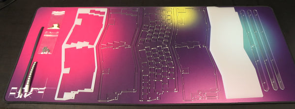
- 1 x Chalice PCB
- 4 x 3mm Acrylic Case Pieces
- 1 x 4.5mm Acrylic Case Pieces
- 3 x 3mm Acrylic Feet
- 4 x Bump-ons
- 6 x 12mm Brass stand-offs
- 1 x 14mm Brass stand-off
- 2 x 10mm Brass stand-offs
- 4 x 6mm Brass stand-offs
- 20 x 5mm Torx screws
Additional Parts Required to Complete
- Pro-Micro Controller (Sea-Micro/Nice!Nano)
Optional Parts
- Female-Male Machined Pin Headers
- Mill-max Pins or Diode Legs
- LiPo Battery (If using Bluetooth)
Tools Required

- Soldering Iron
- T5 Torx Driver
- Solder
- Flux
- Tweezers
Steps
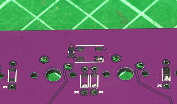
Diodes
Prepare by tinning one pad for each of the diode positions. You can use a little flux here to make the solder flow easier if required.

Using tweezers place one diodes in place and heat the tinned pad to attach the diode. Note the orientation of the diode! The end with the thin white line is the Cathode and it should face south (Towards the K).

Complete this step for all diodes.
RGB LEDs
As with the diodes, tin one of the 4 pads of each LED position. Once done apply flux to all 4 points.
Change the heat of your soldering iron to about 300 degrees – LEDs are sensitive to heat and too hot an iron can kill the LED.

Orientate the LED correctly, with the diamond on the LED towards the L of the silkscreen. Attach the LED by heating up the tinned pad and holding the LED in place. Make sure to push the LED down to ensure it is flat against the PCB.
Solder the other 3 points of the LED as per usual. While this can be done without flux, it is much easier with flux as the solder flows much more easily.
Pin Headers for Pro Micro (Optional)
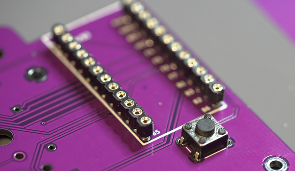
While pin headers are optional, it is highly recommended that you socket your MCU if you plan on change it in the future. For battery installations, the Pin headers are mandatory so you can get access under the Nice!nano.
Ensure that the pin headers are straight by soldering one pin on each row and checking for alignment before soldering all other pins.

Insert Mill-Max pins or diode legs – Push down on each pin to ensure the pin engages in the socket.

Place the MCU on top and solder in place. Components should be facing outwards.
Reset Switch
Insert the reset switch and solder the 4 pins from the rear.
Install Firmware and Test
If using Pro-Micro , Sea-Micro or other compatible Device
Install QMK toolbox – Flash Firmware – Chalice_via.hex
Install Via Software
If using a nice!nano – copy chalice.UF2 file onto the nice!nano drive.
Test switch positions with a pair of tweezers.
Install switches
Stack 4.5mm plate on top of PCB.
Install switches through plate onto PCB. Solder switches at the rear.
Stabilizers can be installed before or after this step - the plate cutouts are large enough that stabilizers can be removed even after the board has been soldered.
Assemble Case
Start by attatching the 2 x 10mm brass stand-offs onto the PCB as per the image below. Screw them in from the back using the provide M2 Torx Screws.
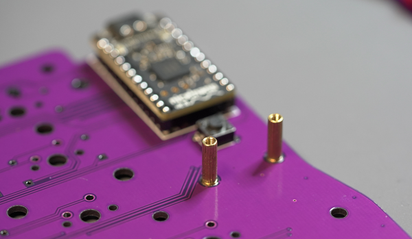
Attach the 12mm Brass-stand offs to the bottom plate as per the image below.
![]()
A single 14mm stand-off is installed at the top right.

If installing using the case feet, install the 6mm stand-offs at the rear and stack the 3 acrylic feet pieces.
